1. Introduction
oday, owing to availability of state-of-the-art microcontrollers and digital signal processors(DSPs), complex control algorithms can be easily implemented to attain the desired system performance [3].But in actual control systems it is difficult to attain the expected result for various factors affect the control systems such as control algorithms itself, capability of implement equipment and states of control circumstance. Except those factors, communication parameters of control systems including baud rate, BER (bit error rate) and synchronization between sub systems also engender great effect .In order to improve precision of control system and make good use of modern control algorithms ,we should pay much more attention on communication in control systems [1].
In several control systems, UART a kind of serial communication circuit used widely. A universal asynchronous receive transmit is an integrated circuit which plays most important role in serial communication. It handles the conversion between serial and parallel data. Serial communication reduces the distortion of a signal therefore makes data transfer between two systems separated in great distance possible [2].
In some complex systems, communications between the master controller and slaver controllers are implemented by serial or parallel port. Parallel communication needs a lot of multi-bit address bus and data bus and it is only convenient for short distance transmission. Serial communication is another way of communication used extensively because of its simple structure and long transmission distance .But sometimes a common serial port could not meet requirements of complex systems with different baud rates equipments even some special baud rate equipments. It is impossible to implement this multi baud rate communication system without a special baud rate converter [3]. A RAM array with separate read and write ports is used to store data .The writer pointer points to the location that will be written next, and read pointer points to the location that will be read currently. A write operation increments the writer pointer and read operation increments the read pointer. On reset, both pointers are rest to zero, the FIFO is empty. The write pointer happens to be the next FIFO location to be written and read pointer is pointing to invalid data. The responsibility of status block is to generate the EMPTY and FULL signals to the FIFO [4]. If the FULL signal is active then the FIFO cannot accommodate more data and if the EMPTY is active then the FIFO cannot provide more data to read out. When writing data into the FIFO "wclk"will be used as the clock domain and when reading data out of the FIFO "rclk" will be used as the clock domain. These both clock domains are asynchronous.
2. c) Factors for the design of Asynchronous FIFO
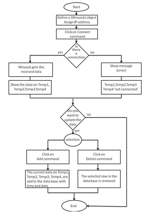
In the designing of asynchronous FIFOs, two important factors are considered. One is how to judge FIFOs status according to the writer pointer and read pointer. The other is how to design circuit to synchronize asynchronous clock domains to avoid metastability. We can use software codes in VHDL to design FPGAs hardware structure, it is easy to create and adjust to satisfy requirements of applications. There are one UART used to communicate with PC or other main MCU and there are also four other UARTs used to communication with sub MCUs [5]. Each channel has two FIFOs one for receiving data and the other for transmitting data. Each FIFO"s depth is 64 bytes. The software flow chart is shown in figure 6. As shown in figure ,when FIFO is full we cannot write any more byte into the FIFO.At this time, the status detector will set CS high to indicate that the FIFO is full and when FIFO is full you cannot write any more byte into the FIFO. At this time, the status detector will set CS high to indicate that the FIFO is full and stop writing to the FIFO. When FIFO is empty we cannot read from it any more. Then the status detector will set empty high to indicate the status of FIFO and stop reading from it [6] [7].
When FIFO is not full or empty it will be written or read data according to the control order. After finishing all write or read operation it will stop until next access is coming.
3. III.
4. Simulation Results
5. a) Simulation And Verification
To verify design of the controller a test bench is written to make verification in modelsim .Data received from the PC or other main MCU will be stored in FIFO"s within FPGA till the controller will set a kind of baud rate according to commands desired. The controller is receiving data and store the data received to different FIFO waiting for read. When sub-controllers are required to receive data at different baud rates, the controller can set each channel at its required baud rate to transmit data. The controller sends data at the same time but at different baud rate. IV.
6. Conclusion
This paper introduces a method to design a method to design a asynchronous FIFO based on FPGA. And using asynchronous FIFO technique implements a multi channel UART controller within FPGA based on SRAM wit high speed and reliability .The controller can be used to implement communications in complex system with different baud rates of sub controllers. And it also can be used to reduce time delays between sub controllers of a complex control system to improve the synchronization of each sub controller. The controller is reconfigurable, so the controller"s fault is that it would be influenced by the radiation from surroundings and by short time pulses easily.