1. Introduction
or many years, the DC machine has taken a special place and distinguished in various industrial applications. This thanks to its simplicity of control due to the natural decoupling between torque and flux, and also its unmatched dynamic performance that let such a machine used in different speeds in various processes. However, the sparks are due to brush-collector contact and the volume of the latter make use of this type of machine useless. [1][2].
On the other hand, the asynchronous squirrelcage which is famous for its strength, high torque mass, and its relatively low cost etc ...., Meanwhile, has enjoyed the favor of the industry since its Nicola Tesla invention by the.end.of last century [3]. However, the dynamics of this type of machine is found to be nonlinear, multi-variable and strongly coupled resulting in rather poor performance in operation with the control V / F = constant. This is unlike the case of the DC machine which is considered as an optimum in point of view simplicity of control compare to the other machines in general that we try to find. This is due to the simplifications offered by the system brushes-collector [2][3].
On the other hand, thanks to the evolution witnessed in the field of power electronics components and the different control techniques applied to the induction machines with squirrel-cage, most of the recent industrial application and control motor drivers are based on induction motor and make such processes as performed as the DC machine. In this sense, the first technique that was used is called "vector control". This technique allows obtaining a decoupled dynamic model similar to the model of the machine to separate DC excitation [4-5-6].
In practice, the use of conventional correction schemes for vector control of induction motor cage where the model is nonlinear and variable parameters seems not so non-robust and efficient [5][6][7]. Indeed, it is known that such control is very sensitive to any changes in the motor rotor resistance, which is why research has for decades referred to other types of controllers more robust among others: those to changing patterns that were used in this. paper.
In the third step, the basic concepts of control structures and variables will be used for the detailed design of a sliding mode control with the prior the first discontinuous control law which is : the boundary layer. Thereafter and to reduce the chattering phenomenon, we propose a new law based on the command softened several ramps.
2. II.
3. Three-Level Npc Vsi Model
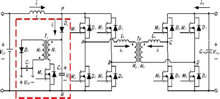
The three phase's three-level NPC VSI structure is illustrated in figure .1. This converter is constituted by . This work is structured in three stages: In the first step, we present the model of the inverter three-level.PWM. The second stage will be devoted to the design of indirect vector control scheme based on a cruise of classic IP. So, in this context and to do this, the basic principles of this type of technical orientation of rotor flux will be presented. three arms. Every arm has four bi-directional switches and two clamping diodes. In controlling mode, the optimal complementary law for the three-level NPC VSI is given the following equation:
3 2 4 1 i i i i B B B B (1)With: is B is the control signal of the semi-conductor TD is of the inverter.
The input voltage of the rectifier, relatively of the neutral point N, is represented by the following system:
1 1 2 3 1 c c . b f b f b f b f b f b f C B A U U V V V (2)Where: b i f 1 and b i f 0 are respectively the upper and lower half-arm connection functions of the inverter.
4 3 0 2 1 1 i i b i i i b i f . f f f . f f (3)With i=1, 2 and 3 is the number of phase.
The performances of this inverter are presented in figure.2. Fig. 2 : Characteristics of the simple output voltage Va of the three phases three levels of cells overlapped VSI and its spectrum with r=0.8 ; m=11. with:
1) modulation index m, 2) and the modulation rate r.
4. III. Control of an Induction Motor a) Model of the induction motor
The equations of the voltage PWM source inverter fed induction motor with current control, in the synchronous reference frame (d-q), using rotor fluxes as state variables are given by [8]: For a rotor-flux orientation, the regulator imposes the orientation of the rotor flux ( r ) with respect to the d-axis, giving r = dr and qr = 0. Substituting these relations in (5), leads to the field-oriented model of the motor which is given by the following equation system:
v ds = L s +R sv ds = L s +R s ds -L s s qs -L R v L dt d T L L T L R v L dt d 2 2 1 1 (6)The corresponding position is given by: e =
IV.
5. VARIABLES STRUCTURES CONTROL
The basic principle of the variables structures control also called the sliding mode control consists in moving the state trajectory of the system toward a predetermined surface called sliding or switching surface and in maintaining it around this latter with an appropriate switching logic. This is similar to a feedforward controller that provides the control that should be applied to track a desired trajectory, which is in this case, the user-defined sliding surface itself. So, the design of a sliding mode controller has two steps, namely, the definition of Concerning the development of the switching logic, it is divided into two parts, the equivalent control U eq and the attractivity or reachability control U n . The equivalent control is determined off-line with a model that represents the plant as accurately as possible and calculated by imposing the derivative of sliding mode surface equal to zero. If the plant is exactly identical to ) ( S the model used for determining U eq and there are no disturbances, there would be no need to apply an additional control U n . However, in practice there will be discrepancy between the model and the actual system control. Therefore, the control component U n is necessary and it will always guarantee that the state is attracted to the switching surface by satisfying the following attractivity condition.
The rotor flux is estimated by means of stator current and speed measurements (direct method) as follows:
0 ) ( ) ( S S(8)Therefore, the basic switching law is of the form:
U =U eq + U n (9)With: U n = M(S): the magnitude of the attractivity control law U n , Sgn: the sign function.
In a conventional the variables structures control (VSC), the reachability control generates a high control activity as it depends on the magnitude since it was first taken as constant, a relay function, which is very harmful to the actuators and may excite the unmodeled dynamics of the system. This is known as a chattering phenomenon. Ideally, to reach the sliding surface, this phenomenon should be eliminated [9][10]. However, in practice, chattering can only be reduced.
To reduce chattering was to introduce a boundary layer around the sliding surface and to use a smooth function to replace the discontinuous part of the control action as follows [8][9][10]: (10) Fig. 4 : Sliding mode with boundary layer and the modified switching law.
The constant K is linked to the speed of convergence towards the sliding surface of the process the reaching mode). Compromise must be made when choosing this constant, since if K is very small the time response is important, whereas when K is too big, the chattering phenomenon increases so, in this paper, we proposed an approach which is able to reduce this latter and will be described in the following section.
V.
6. Control Softened Several Ramps
In order to further reduce the chattering, the idea consists to approach gradually the control state of the sliding mode surface. So, we propose to use a softened several ramp discontinuous control law given in eq.11. Thus, this control law must be based on the approach of the state toward the surface in the region that borders the latter, and that following several slopes with a pass through the origin in the (S (x ), Un) in order to avoid a discontinuity of operation as it is shown in figure .5 [11]. The expression that corresponds to it is given by: (11) with:
) ( ). ( s sign S M U n)) ( Sgn( ) ( S M ) ( MReduction of The Chattering by Using Softned Several Ramps Control Law in the Field-Oriented Control Process of an Induction Motor
) (x S K if |S(x)| < U n = ) ( x S Sgn K if |S(x)| > S - U n K +K2 M(S) = ((K 2 -K 1 )/( 2 -1 )). S(x) < |S(x)| < + ( K 1 / 1 ).S(x) -1 <|S(x)| < 1 ((K 1 -K2) 1 /( 1 -2 )). S(x) -2 < |S(x)| < -1 -K 2 |S(x)| < -2To satisfy the stability condition of the system, the gains K 1 and K 2 should be taken positive by selecting the appropriate values.
7. VI.
8. CONCEPTION OF THE SPEED VARIABLES STRUCTURES CONTROLLER OF THE CASCADE SCHEME
In this paper, only the PI speed controller of the figure .3 is replaced by variables structures one. Its corresponding parameters are defined as follows: a) Design of the switching surface The sliding mode surface is defined as: Concerning the discontinuous control law qsn it is considered as it was defined in eq.10 and eq.11 respectively.
S( ) = dt m ref ref 1(12) With:9. VII. VALIDATION OF THE CASCADE SLIDING MODE CONTROLLERS
In order to verify the effectiveness of the softened several ramps control law (eq.11) compared to the boundary layer one (eq. 10), a simulation of the dynamic of the process is done by considering the following tests:
The first test concerns a no-load starting of the motor with a reference speed ref = 100 rad/sec. Then a torque load (T L = 10 Nm) is applied at t = 0.5 sec. The results are shown in "fig. 6 and 7".
Note that the parameters of the induction motor used are given in Appendix. The step changes in the load torque and the reverse of speed response cause step changes in the torque response without any effects on the fluxes responses, which are maintained constant, due to the decoupled control system between the torque and the rotor flux. Thus, the aim of the field-oriented control is achieved, and the introduction of perturbations is immediately rejected by the control system. The chattering phenomenon appears in the torque response due to the discontinuous characteristic of the controller and a marked reduction of such a phenomenon with the second discontinuous control law is noticed. So, we can see that our objective is attempted with great success.
On the other hand, in order to test the robustness of this control towards the parameters variation especially the rotor's resistance which could leads to the loose of the vector control of the motor, we made a variation of rotor resistance by 50% from its nominal value. The results are given in figures (8) From the obtained waveforms, it is clearly shown that the robustness of our system toward parameter's variations and external perturbation is ensured in all the sliding mode control processes which confirms the ability of these kind of structures variables control techniques to ensure the tracking and the robustness as it is cited by numerous other works. VIII.
10. Global Journal of Researches in Engineering
11. Conclusion
The proposed approach has revealed very interesting features. In fact, the combination of the nonlinear control with the field oriented control maintains an effective decoupling between speed and flux for the whole range of speed which allows to obtain high dynamic performances for constant flux operation similar to that of dc motors. Further, these high performances are maintained above the nominal speed for the constant power operation, which is not the case in the conventional field oriented control. The addition of the sliding mode controllers has improved the robustness towards internal parameter variations, modelling uncertainties and external disturbances.