1. Introduction
ryogenics comes from the Greek word "kryos", which means very cold or freezing and "genes" means to produce. A Cryocooler is closed cycle cooler of a device which is used to cool inside the environment of anything and increasing need in cryogenic temperature in research and high conductivity during the last decade caused a rapid development of cryocoolers. In a country like India [1],
The cost of liquid Helium and liquid Hydrogen is increasing, cryocoolers can play a very important role [1]. Its Refrigeration powers vary from about (0.15 W to 1.75 w). The ability of the device to cool its interior environment depends largely on the thermodynamic properties of the gas circulating through the system. Cryocooler may be classified into different types of pulse tube which called various name, the important factors are discussed that have brought the pulse tube refrigerator to its current position as one of the most promising cryocoolers for a wide variety of applications [2].
2. II.
3. Applications
The main requirement is it's cooled below 120k which is use in various applications, area is very large. Cryocoolers are refrigerating machines, which are able to achieve and to maintain cryogenic temperatures [3]. The recuperative coolers use only recuperative heat exchangers and operate with a steady flow of refrigerant through the system. The compressor operates with a fixed inlet pressure and a fixed outlet pressure. If the compressor is a reciprocating type, it must have inlet and outlet valves (valve compressor) to provide the steady flow. Scroll, screw or centrifugal compressors do not need valves to provide the steady flow [4]. Figure2 shows schematics of the most common recuperative cryocooler cycles. Expansion of the liquid in the JT capillary, orifice, or valve is relatively efficient and provides enough of a temperature drop that little or no heat exchange with the returning cold, expanded gas is required. Thus, a very efficient recuperative heat exchanger is required to reach cryogenic temperatures.
4. Classification of Cryocooler
5. i. Joule Thomson Cryocoolers ii. Brayton Cryocoolers
In Brayton cryocoolers (sometimes referred to as the reverse Brayton cycle to distinguish it from a heat engine) cooling occurs as the expanding gas does work. Figure shows a reciprocating expansion engine for this purpose, but an expansion turbine supported on gas bearings is more commonly used to give high reliability. According to the First Law of Thermodynamics the heat absorbed with an ideal gas in the Brayton cycle is equal to the work produced.
The Brayton cycle is commonly used in large liquefaction plants. For small Brayton cryocoolers the challenge is fabricating miniature turbo expanders that maintain high expansion efficiency. The expansion engine provides for good efficiency over a wide temperature range, although not as high as some Stirling and pulse tube cryocoolers at temperatures above about 50 K. The low-pressure operation of the miniature Brayton systems requires relatively large and expensive heat exchangers [7]. In regenerative types the refrigerant undergoes an oscillating flow or an Oscillating pressure analogous to an AC electrical system. The compressor and the pressure Oscillator for the regenerative cycles need no inlet or outlet valves. The regenerator has only one flow channel, and the heat is stored for a half cycle in the regenerator matrix, which must have a high heat capacity. The performance of the regenerative type cryocoolers is dependent on the phase difference between the pressure and mass flow rate phases. Helium is the refrigerant of choice for most regenerative type cryocoolers [8].
6. 2012
May gas in the proper phase relationship with the pressure oscillation. When the displacer is moved downward, the helium gas is displaced to the warm end of the system through the regenerator. The piston in the compressor then compresses the gas, and the heat of compression is removed by heat exchange with the ambient.
The Joule-Thomson cryocoolers produce cooling when the high pressure gas expands through a flow impedance (orifice, valve, capillary, porous plug), often referred to as a JT valve. The expansion occurs with no heat input or production of work, thus, the process occurs at a constant enthalpy. The heat input occurs after the expansion and is used to warm up the cold gas or to evaporate any liquid formed in the expansion process [5]. The main advantage of JT cryocoolers is the fact that there are no moving parts at the cold end. The cold end can be miniaturized and provide a very rapid cool down. This rapid cool down (a few seconds to reach 77 K) has made them the cooler of choice for cooling infrared sensors used in missile guidance systems. These coolers utilize a small cylinder pressurized to about 45 M Pa with nitrogen or argon as the source of high pressure gas. Miniature finned tubing is used for the heat exchanger. An explosive valve is used to start the flow of gas from the high pressure bottle. The higher boiling point components must remain a liquid at the lowest temperature [6].
Next the displacer is moved up to displace the gas through the regenerator to the cold end of the system. The piston then expands the gas, now located at the cold end, and the cooled gas absorbs heat from the system it is cooling before the displacer forces the gas back to the warm end through the regenerator.
In an ideal system, with isothermal compression and expansion and a perfect regenerator, the process is reversible. Thus, the coefficient of performance COP for the ideal Stirling refrigerator is the same as the Carnot COP given by (1) Where the net refrigeration power is, is the power input, T c is the cold temperature, and T h is the hot temperature. The occurrence of T c in the denominator arises from the PV power (proportional to T c ) recovered by the expansion process and used to help with the compression. Practical cryocoolers have COP values that range from about 1 to 25% of the Carnot value.
Stirling cycle consists of four thermodynamic processes acting on the working fluid: Points 1 to 2, Isothermal Expansion. Points 2 to 3, Constant Volume (known as isovolumetric or isochoric) heat removal. Isothermal Compression (Point 3 to 4), Points 4 to 1, Constant Volume (known as iso -volumetric or isochoric) heat addition [9]. 2. The piston moves down to compress the gas (Helium) in the pulse tube. It flows through the orifice into the reservoir and exchanges heat with the ambient through the heat exchanger at the warm end of the pulse tube. The flow stops when the pressure in the pulse tube is reduced to the average pressure. 3. The piston moves up and expands the gas adiabatically in the pulse tube. 4. This cold, low pressure gas in the pulse tube is forced toward the cold end by the gas flow from the reservoir into the pulse tube through the orifice. As the cold gas flows through the heat exchanger at the cold end of the pulse tube it picks up heat from the object being cooled. The flow stops when the pressure in the pulse tube increases to the average pressure. 5. The cycle then repeats. The displacer is eliminated. The proper gas motion in phase with the pressure is achieved by the use of an orifice and a reservoir volume to store the gas during a half cycle. The reservoir volume is large enough that negligible pressure oscillation occurs in it during the oscillating flow. The oscillating flow through the orifice separates the heating and cooling effects just as the displacer does for the Stirling and Gifford McMahon refrigerators. The orifice pulse tube refrigerator (OPTR) operates ideally with adiabatic compression and expansion in the pulse tube [10]. In the pulse tube refrigerator the cooling actually occur in the oscillating pressure environment. The heat is absorbed and rejected at the two heat exchangers. It is a cyclic process.
Because PTR operates in steady periodic mode, the thermodynamic properties such as enthalpy flow , heat flow and power are evaluated in the form of cyclic integrals. The appropriate instantaneous thermodynamic properties are integrated over the entire cycle and divided by the period of that cycle to obtain the cyclic averaged quantity of interest [11]. For example, the compressor power is evaluated from the following integration.
(
)2Where f is frequency is period of the cycle, P and V, are instantaneous pressure and volume respectively. The average enthalpy flow over one cycle and average heat flow rate are also calculated similarly.
V.
7. Ptr Efficieny
In an ideal PTR the only loss is the irreversible expansion through the orifice. The irreversible entropy generation there is a result of lost work that otherwise could have been recovered and used to help with the compression [12]. All other components are assumed to be perfect, and the working fluid is assumed to be an ideal gas. The COP for this ideal PTR is given by VI.
8. Component Development a) Expander
The expander assembly is the key cooling system component, enabling the actualization of a cryocooler with high efficiency, compact size, and low mass. The expander is a transducer that operates by creating an electrostatic force between two electrodes in a precision capacitor and allowing pressurized gas to separate the electrodes. The gas does work against the electrostatic force by separating the electrodes. This work is eventually dissipated as Joule heating in a warm load resistor. By doing work and removing it from the system, the expansion process can be carried out at nearly isentropic state and the dissipated energy provides an efficient means to reduce the gas temperature.
The expander is configured in an opposing piston arrangement and as gas is expanded on one side, the already cooled gas is expelled on the opposite side. In figure one side of the expander is being filled by opening a series of valves to the high pressure side of the system, figure the gas is expanded in the left side while the previously expanded and cooled gas on the right side is expelled to the low pressure side of the system.
( ) ( ) C c carnot o h c C d c c ideal o d h h Q T C O P W T T Q PV T C O P W PV T = = ? = = =wear mechanisms by balancing the forces and resultant moment on the orbiting scroll while allowing the fixed Scroll to translate radically and axially, thereby minimizing contact forces between surfaces. Balance is achieved by configuring two orbiting scrolls mounted from a common base plate and mechanically driving the base plate from the outer edge or from a rigid central hub. Using this method, the forces can be reacted about the base plate producing no net off axis torque that can contribute to seal or wear.
To balance the axial forces that act on the scroll tips, an external gas pressurization scheme is employed. A pressurized gas volume is maintained external from the compression space on the backside of the fixed scroll to apply an axial force. The force on the fixed scroll will then just slightly exceed the separation force acting between the orbiting and fixed scrolls from the compressed gas. This applies a well controlled, Cryocooler uses a series of heat exchangers to achieve its thermodynamic efficiency, these include an after cooler to reject the heat generated in the compression process, recuperative counter flow heat exchanger between the high and low pressure gas streams, and cold end heat exchanger to interface with the element that are cooled. Effective heat exchange in each of the exchangers is paramount to achieving high system efficiency, but recuperate presents the largest challenge in terms of realizing a compact design that has high net effectiveness [13].
H Q W Q H9. d) Regenerator
The regenerator is the most important component in pulse tube refrigerator. Its function is to absorb the heat from the incoming gas during the forward stroke, and deliver that heat back to the gas during the return stroke. Ideally, PTC regenerators with no pressure drop and a heat exchanger effectiveness of 100% are desired, in order to achieve the maximum enthalpy flow in the pulse tube. The performances of the real regenerators are of course far from ideal. Stainless steel wire screens are usually selected as the regenerator packing material, since they offer higher heat transfer areas, low pressure drop, high heat capacity, and low thermal conductivity.
10. e) Rotary Valve
It is used to switch high and low pressure from a helium compressor to the pulse tube system. The high and low pressure of helium compressor are connected to the rotary valve through the quick disconnect couplings. The rotary valve has a Rulon part which is made to rotate with the help of a synchronous motor against an aluminum block with predefined passages connecting the high and low pressures from the helium compressor [14]. The rotational frequency of the synchronous motor is controlled using an inverter drive.
The rotary valve has been designed to produce pressure wave in the frequency range from 1Hz to 3Hz. A typical design of rotary valve is shown in Fig 10. Suppose that in the beginning of the cycle the gas parcel at position X 1 has temperature T 1 and the temperature distribution of the wall is given as line 1-2. Consider the first half cycle where the pressure increases from the lowest to the highest. During this period, the gas parcel flows towards the closed end of the pulse tube to position X 2 undergoing an adiabatic process, hence its temperature increases to T 3 . Since T 3 T 2 , therefore heat is rejected to the wall by the gas parcel until temperature of the gas parcel equals to that of the wall T 2 . During the next half cycle, this gas parcel flows backward. This is an adiabatic expansion process where the temperature of the gas parcel decreases to T 4 . Since T 4 T 1 , the gas parcel has refrigeration effect at the position X 1 . This is so called surface heat pumping theory [15]. Where the period of the cycle is, C p is the heat capacity.
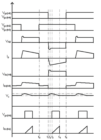
The pharos quantities and are mass flow rate and temperature respectively. ). Mass flow rate shown in right to right hand place shown in figure 14),On the other hand, if an oscillating mass flow rate is out of phase with oscillating gas temperature T, then little or no enthalpy flow will exist in the pulse tube, which results in minimum cooling. Figure, depicts two examples of phase shift between gas temperature and mass flux.
The first example in Fig. 13 demonstrates a case where the mass flow rate and the temperature oscillations are about 90 degrees apart. In this circumstance, little or no enthalpy flow takes place. In fact, with temperature and the time mass flow rate being 90 degrees out of phase, one phase quantity will always be zero when the other one is at its peak. Thus, out of phase relationships tend to produce poor refrigeration due to minimum enthalpy flow in the pulse tube. On the other hand, if the mass flow rate and the temperature oscillations are in phase as illustrated in the second example (Fig. 14), good enthalpy flow can exist in the pulse tube. Thus in phase and out phase are the two extreme conditions. In actual pulse tube there are exists same phase difference between the phase quantities [17]. The working process of the pulse tube refrigeration system is very complex due to the unsteady, oscillating compressible gas flow, the porous media in regenerator, the presence of the orificereservoir, the double inlet valve etc. The cooling effect at cold end of the pulse tube occurs due to compression and expansion of the gas column lies somewhere between the adiabatic and isothermal processes, and may be assumed to be a polytrophic process. To understand the basic phenomenon responsible for the m production of cold effect at the pulse tube section, two limiting cases adiabatic and isothermal processes involving ideal gas have been considered. Both these models are approximate models which are dealt separately.
The following assumption has been made with adiabatic behavior of the gas. The regenerator, the cold end and hot end heat exchangers have been assumed to be perfect. That means that the regenerator will always maintain a constant temperature gradient between its hot and cold ends at steady operation [18]. And heat addition at cold end heat exchanger and heat rejection at hot end heat exchanger of pulse tube occur at constant temperature at steady conditions. The pressure wave in the pulse tube is provided with a compressor directly coupled to the hot end of the regenerator. This design is more compact and more efficient than the valve compressor with gas distributor design [19]. The compressor cylinder has been assumed to be adiabatic in the analysis, since each of the compression and expansion processes occurs in such a short period of time that little heat exchange between the gas and the cylinder wall can be affected. The gas adiabatically compressed in the cylinder is assumed to be cooled to room temperature by the adjacent after cooler. The after cooler has been assumed to be perfect, so that the temperature of the gas leaving it is always equal to its wall temperature.
11. iii. Change in Compressor Volume
Sinusoidal variation has been taken for the compressor cylinder volume variation. (7) Where V 0 = clearance volume, V S = stroke volume and f = frequency Applying the first law of thermodynamics to the control volume drawn around the volume swept by the piston in the cylinder and Compressor pressure variation is expressed as (8) Fig. 16 : control volume cylinder iv. Pressure Variation at the Pulse Tube Pulse tube pressure variation is a function of compressor pressure variation. So the pressure variation in the pulse tube can be derived in terms of compressor pressure variation along with various mass flow rate involved in the system. The cold end mass flow rate equation derived earlier is (9) Where T C and T H are the temperatures at cold end and hot end respectively and R is a gas constant. In case of double inlet pulse tube refrigerator, the mass flow rate through the double inlet valve (DI) is due to the pressure difference between compressor and pulse tubes [20]
P P P P a t x t x ? ? ? ? ? ? + ? + = ? ? ? ? 2 , p a ? ? ? = = 0 ( ) [1 sin(2 )] 2 S cp V V t V ft = + + ? [ ] cp cp p c p c p dp dV mc RT P dt dt = ? ? t t H c h C c V dp T m m T RT dt ? = + di m dhx V c m rg m drg dcx t t rg c c r g V V dP dP m m RT dt RT dt = + + +The cold end mass flow rate is given as,
( )
0 1 h t t c di dhx C c T V dP m m m V T R T d t ? = ? + +Compressor out let mass flow rate is given as:
v. Pressure Variation at the Reservoir Pressure variation at the reservoir is due to the mass flow through the orifice and it is given as: (13) vi. Mass Flow through Regenerator Mass flow in the regenerator has been evaluated through Argon's equation, (14) Where the porosity of the porous medium is, is the density of the fluid, d h the hydraulic diameter, is the dynamic viscosity of the fluid and A rg is the cross section area of the regenerator. Assuming dx L rg (length of regenerator) and dp p (P cp P t )
vii. Mass Flow through Orifice Mass flow through the orifice has been assumed as a nozzle flow, calculated from well known formula for a nozzle with a correction factor [21]. (15) Where P t P r (16) Where P t P r viii. Mass Flow Rate through Double Inlet Valve Mass flow rate through double inlet valve has also been assumed as nozzle flow similar to that in the orifice. Here the mass flow occurs due to pressure differences between compressor and the pulse tube. Therefore, mass flow rate has been calculated as (17) Where P cp P t (18) Where P cp P t d) Second Order of Isothermal Model Analysis In this model, the compression and expansion processes are considered as isothermal. It shows higher efficiency than the adiabatic or any other model of the pulse tube. For the purpose of analysis, a pulse tube refrigerator system is divided into a few subsystems, which are coupled to each other. Different researchers have used different schemes for dividing the full pulse tube refrigerator into subsystems. The pulse tube device has been divided into six open subsystems. Three of them exchange work, heat and mass with the surroundings (compressor, cold and hot volumes), while the others exchange mass only (regenerator, double inlet valve and orifice reservoir). It has been assumed that all heat exchanges are at constant temperature and that temperature of all subsystems exchanging heat is equal to those of the heat reservoirs. Another condition is that mechanical equilibrium is realized in each part of the device. These conditions lead to the model presented in Figure 17. The system described in the figure consists of six opened subsystems as(In the figure point 1 is compressor, 2 is after cooling, 3 is regenerator, 4 is cold end, 5 is hot end, 6 DI valve,7 is orifice and 8 is reservoir) [22], [23]. ) i. Governing Equations
0 pcp h dac p d i d i t Ch drg dcx t dhx rg c c c d T V R mc m R m m dP T T dt dt V V V V T T T T ? ? ? ? ? = + + + ( ) 0 1 cp h r dp m RT dt V = ? 2 2 3 ( ) 600(1Figure 18 shows a control volume which represents an isothermal variable volume. iii. For Pulse Tube Similarly to that in compressor, the pulse tube flow has been assumed to be a piston like flow. In other words, the displacer of the Stirling or the GM cryocooler has been converted into a gas piston. The pulse tube has been divided into two distinct volumes, one for cold volume V c and the other for the hot volume V h at uniform temperature to ensure the reversibility of the model [26], [27]. (22) iv. For Cold Volume (23) v. For Hot Volume (24) (25) The pressure variation in the pulse tube is the addition of two pressure variations in cold and hot volume.
12. ( )
13. Conclusion
In this study, first part is basic study of different types of cryocooler. Result is pulse tube type cryocooler is more reliable, no vibration etc. Second part, PTR efficiency method, flow properties, characteristic analysis and mathematical analysis use to find PTR different kind of equation to help for simulation techniques and various type of software such that fluent, CFD, and MATLAB etc. Mathematical analysis also use to find improved design and modification, it has now become the most efficient cryocooler for a given size. It is suitable for a wide variety of application from civilian to government to military and from ground equipment to space systems.


| 2 | ? | + | 1 | |||||||||||||||||||||||
| m | di | = ? | di di C A | 2 | ? | -1 ? | 2 h RT cp P | t c p P P | ? | - | t c p P P | ? | ||||||||||||||
| rg m | = | ?? | rg d d rg L ? h | ? ? | ? | cp P P t ? | ||||||||||||||||||||
| 2 | ? | + | 1 | |||||||||||||||||||||||
| m | 0 | = | - | 0 C A d | 2 | ? | -1 ? | 2 h RT t P | t r P P | ? | - | t r P P | ? | |||||||||||||
| 2 | ? | + | 1 | |||||||||||||||||||||||
| m | 0 | = | d C A | 0 | 2 | ? | -1 ? | 2 h R T t P | t r P P | ? | - | t r P P | ? | |||||||||||||
| 2 | ? | 1 + | ||||||||||||||||||||||||
| m | di | = | di di C A | 2 | ? | -1 ? | 2 h RT cp P | t c p P P | ? | - | t c p P P | ? | ||||||||||||||