1. INTRODUCTION
ibration of aircraft steering systems has been a problem of great concern since the production of first airplanes. Shimmy is an oscillatory motion of the landing gear in lateral and torsional directions, caused by the interaction between the dynamics of the tire and the landing gear, with a frequency range of 10-30 Hz. Though it can occur in both nose and main landing gear, the first one is more common. Shimmy is a dangerous condition of self -excited oscillations driven by the interaction between the tires and the ground that can occur in any wheeled vehicle. Problem of shimmy occurs in ground vehicle dynamics and aircraft during taxiing and landing. In other words, shimmy takes places either during landing, take-off or taxi and is driven by the kinetic energy of the forward motion of the aircraft. It is a combined motion of the wheel in lateral, torsional and longitudinal directions.
2. II.
3. SHIMMY
Shimmy can occur in steerable wheels of cars, trucks and motorcycles, as well as trailers and tea carts. Invehicle dynamics, shimmy is the unwanted oscillation of a rolling wheel about a vertical axis. It can occur in taxiing aircraft, as well. In the case of a shopping cart wheel, it is caused by the coupling between transverse and pivot degrees of freedom of the wheel. In the case of landing gear, shimmy is the result of the coupling between tire forces and landing gear bending and Author : Istanbul Technical University, Department of Aeronautical Engineering, Maslak, Istanbul, Turkey. E-mail : [email protected], [email protected] torsion. In other words, basic cause of shimmy is energy transfer from tireground contact force and vibration modes of the landing gear system. Shimmy is an unstable phenomenon and it occurring with a certain combination of parameters such as mass, elastic quantities, damping, geometrical quantities, speed, excitation forces and nonlinearities such as friction and freeplay. It is difficult to determine shimmy analytically since it is a very complex phenomenon, due to factors such as wear and ground conditions that are hard to model. Small differences in physical conditions can lead to extremely different results. For example, it is reported in [1] that a new small fighter aircraft whose name is withheld, has displayed to vibrations during low and high speed taxi tests and first several landings and take -offs, but shimmy vibrations with frequencies in the range 22-26 Hz were experienced during next several landings and take-offs at certain speeds, especially during landing. This demonstrates the effect of wear on landing gear shimmy. In the reported case, it was seen that tightening the rack too tight against the pinion prevented the wheel from turning, while tightening it less tight caused the vibration to disappear but reappear in the following flights.
Ground control of aircraft is extremely important since severe shimmy can result in loss of control or fatigue failure of landing gear components. Vibration of aircraft steering systems deserves and has gained attention since shimmy is one of the most important problems in landing gear design. Shimmy is reported to be due to the forces produced by runway surface irregularities and nonuniformities of the wheels [2][3][4][5]. Modeling of aircraft tires presents similar challenges to those involved in modeling automotive tires in ground vehicle dynamics, on a much larger scale in terms size and loads on the tire [6]. Shimmy is a complex phenomenon influenced by many parameters. Causes of shimmy can be listed as follows [2,[7][8][9][10].
Insufficient overall torsional stiffness of the gear about the swivel axis Inadequate trail, since positive trail reduces shimmy Improper wheel mass balancing about the swivel axis Excessive torsional freeplay Low torsional stiffness of the strut Flexibilities in the design of the suspension Surface irregularities Nonuniformities of the wheels III.
4. DETECTION AND SUPPRESSION OF SHIMMY
Shimmy is a great concern in aircraft landing gear design and maintenance. Prediction of nose landing gear shimmy is an essential step in landing gear design because shimmy oscillations are often detected during the taxi or runway tests of an aircraft, when it is no longer feasible to make changes on the geometry or stiffness of the landing gear. Although shimmy was observed in earlier aircraft as well, there were no extra shimmy damping equipments installed. Historically, France and Germany tended to deal with shimmy in the design phase, while in United States, the trend was to solve the problem after its occurrence. Currently, the general methodology is to employ a shimmy damper and structural damping. A shimmy damper, acting like a shock absorber in a rotary manner, is often installed in the steering degree of freedom to damp shimmy. It is a hydraulic damper with stroke limited to a few degrees of yaw. A shimmy damper restrains the movement of the nose wheel, allowing the wheel to be steered by moving it slowly, but not allowing it to move back and forth rapidly. It consists of a tube filled with hydraulic fluid causing velocity dependent viscous damping forces to form when a shaft and piston are moved through the fluid. Oleo-pneumatic shock absorbers are the most common shock absorber system in medium to large aircraft, since they provide the best shock absorption ability and effective damping. Such an absorber has two components: a chamber filled with compressed gas, acting as a spring and absorbing the vertical shock and hydraulic fluid forced through a small orifice, forming friction, slowing the oil and causing damping. Another common cure is to replace the tires even though they may not be worn out [10][11][12].
Shimmy started being investigated in 1920's both theoretically and experimentally and soon it became clear that it is caused not by a single parameter but by the relationships between parameters. Effects of acceleration and deceleration on shimmy have been reported to be examined, and the accelerating system is found to be slightly less stable [13]. Number of publications available in literature on landing gear shimmy is limited because many developments are proprietary and are not published in literature.
IV.
5. LITERATURE SURVEY
Many papers have been published addressing shimmy as a vehicle dynamics problem. In that perspective, tire is the most important item, and tire models have been investigated. [13] examines the wheel shimmy problem and its relationship with investigation of tire parameter variations in wheel shimmy, by considering the shimmy resulting from the elasticity of a pneumatic tire, particularly in taxiing aircraft. [14] is on the application of perturbation methods to investigate the limit cycle amplitude and stability of the wheel shimmy problem. [7] deals with the shimmy stability of twin-wheeled cantilevered aircraft main landing gear. The objective in [15] is to develop software on assessing shimmy stability of a general class of landing gear designs using linear and nonlinear landing gear shimmy models. [16] studies the periodic shimmy vibrations and chaotic vibrations of a simplified wheel model using bifurcation theory. [17] is on tire dynamics and is a development to deal with large camber angles and inflation pressure changes. [18] is another study on tire dynamics, where stability charts show the behavior of the system in terms of certain parameters such as speed, caster length, damping coefficient and relaxation length. [19] is an experimental study on wheel shimmy where system parameters are identified, stability boundaries and vibration frequencies are obtained on a test rig for an elastic tire. Dependence of shimmy oscillations in the nose landing gear of an aircraft on tire inflation pressure are investigated in [20]. The model derived in [21] is used and it is concluded that landing gear is less susceptible to shimmy oscillations at inflation pressures higher than the nominal.
Transverse vibrations of landing gear struts with respect to a hull of infinite mass have been studied theoretically in [22]. Similarly, [23] presents a nonlinear model describing the dynamics of the main gear wheels relative to the fuselage.
Lateral dynamics of nose landing gear shimmy models has gained some attention. Lateral response of a nose landing gear has been investigated in [10] where nonlinearities arise due to torsional freeplay. In [24], lateral response to ground-induced excitations due to runway roughness is taken into consideration as well. Lateral stability of a nose landing gear with a closed loop hydraulic shimmy damper is presented in [12]. Closed form analytical expressions for shimmy velocity and shimmy frequency are derived in regard to the lateral dynamics of a nose landing gear in [25].
A dynamic model of an aircraft nosegear is developed in [9] and effects of design parameters such as energy absorption coefficient of the shimmy damper, the location of the center of gravity of the landing gear, shock strut elasticity, tire compliance, friction between the tire and the runway surface and the forward speed on shimmy are investigated. It is shown in [26] that dry friction is one of the principal causes of shimmy. Bifurcation analysis of a nosegear with torsional and Stability analysis of a landing gear mechanism with torsional degree of freedom longitudinal tire forces, vehicle motions and normal load oscillations. [8] compares different dynamic tire models for the analysis of shimmy instability. [3] is an lateral degrees of freedom is performed in [21]. Similarly, bifurcation analysis of a nosegear with torsional, lateral and longitudinal modes is performed in [27].
( D D D D ) D 2012 ebruary FIn a more mathematical study, incremental harmonic balance method is applied to an aircraft wheel shimmy system with Coulomb and quadratic damping [28] and amplitudes of limit cycles are predicted.
Theoretical research on shimmy has a long history, with the initial focus on tire dynamic behavior because tires play an important role in causing shimmy instability. Theories on tire models can be divided into stretched string models and point contact models. In the stretched string model proposed by von Schlippe, the tire centerline is represented as a string in tension, the tire sidewalls are represented by a distributed spring where the string rests and the wheel is represented by a rigid foundation for the spring. Pacejka has proposed replacing the string by a beam. The point contact method assumes the effects of the ground on the tire act at a single contact point and is much easier to implement in an analytical model.
V.
6. MATHEMATICAL MODEL a) Landing gear model
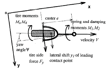
In this study, stability of a landing gear model with torsional degree of freedom is analyzed. The nonlinear mathematical shimmy model presented in [11], [29] and [30] describes the torsional dynamics of the lower parts of a landing gear mechanism and stretched string tire model. Figures 1 a and b show the physical and mathematical nose landing gear models. Dynamics of the lower part of the landing gear is described by a second order ordinary differential equation for the yaw angle about the vertical axis z, while the dynamics of the tire modeled with respect to the stretched string tire model is described by a first order ordinary differential equation for the lateral tire deflection y. b. shimmy dynamics model [29].
Where I z is the moment of inertia about the z axis, M 1 is the linear spring moment between the turning tube and the torque link,
4 3 2 1 M M M M I z + + + = ? (1)M 2 is the combined damping moment from viscous friction in the bearings of the oleo-pneumatic 2 shock absorber and from the shimmy damper, M 3 is the tire moment about the z axis and M 4 is the tire damping moment due to tire tread width.. M 1 and M 4 are external moments. M 3 and M 4 are caused by lateral tire deformations due to side slip. M 3 is composed of M z , tire aligning moment about the tire center, and tire cornering moment eF y . F y is the wheel cornering force or the sideslip force acting with caster e as lever arm.
Stability analysis of a landing gear mechanism with torsional degree of freedom Where k is the torsional spring rate, c is the torsional damping constant, v is the taxiing velocity and is the tread width moment constant defined as [29] Fy and M z depend on the vertical force F z and slip angle . Tire sideslip characteristics are nonlinear. Cornering force Fy and vertical force F z are related as Where is the limiting slip angle or the limit angle of tire force and sign is the sign function defined as Slip angle may be caused by either pure yaw or pure sideslip. Pure yaw occurs when the yaw angle is allowed to vary while the lateral deflection y is held at zero. Pure sideslip, on the other hand, occurs when the lateral deflection y is allowed to vary as the yaw angle is held at zero [11].
? k M = 1 ( 2 ) ? c M = 2 ( 3 ) y z eF M M ? = 3 ( 4 ) ? ? v M =Where B,C, D and E are functions of the wheel load, slip angle, slip ratio and camber. B and E are related to vertical force F z , C is the shape factor and D is the peak value of the curve.
Aligning moment M z is defined using a half-Where g the limiting angle of tire moment. b) Tire model Tire is modeled using the elastic string theory. Lateral deflection of the tire is described as [11,29] Ground forces are transmitted to the wheel through the tire, and these forces acting on the tire footprint deflect the tire. Elastic string theory states that lateral deflection y of the leading contact point of the tire with respect to tire plane can be described as a first order differential equation given by (13). This equation is derived as follows. Tire sideslip velocity V t is expressed as Where is the time constant, is the relaxation length, which is the ratio of the slip stiffness to longitudinal force stiffness.
z F F c a ? ? 2 15 . 0 ? = ( 6 ) ? ? F z y c F F = , for ? ? ? (7) ( ) ? ? ? sign c F F F z y = , for ? ? > (8) ( ) ? ? > = ? ? ? ? ? if , 1 if , 1 sign ( 9 ) ( ) ( ) { } [ ] ? ? ? B B E B C D F y arctan arctan sin ? ? = (10)Plots of Fy / Fz versus will not be presented here due to lack of space, but they have similar characteristics when obtained using either (7) and (8) or the Magic Formula, thus the simple approximations given by ( 7) and ( 8) are used instead of the complicated Magic Formula. Only force and moment derivatives are needed as parameters for (7) and (8).
7. (
)
? ? ? a e v y v y ? + = + ( 1 3 ) ? y y V t + = ( 1 4 ) V ? ? =The tire also undergoes yaw motion, leading to a yaw velocity V r which is approximated as As the wheel rolls on the ground, Substituting ( 14) and ( 15) into ( 16) yields (13).
8. (
)
? ? a e v V r ? + = ( 1 5 ) r t V V = ( 1 6 )An equivalent side slip angle caused by lateral deflection is used to compute cornering force F y and aligning moment M z and is approximated as Equations ( 1), ( 13) and ( 17) constitute the governing equations of the torsional motion of the landing gear and include nonlinear tire force and moment. Parameters of a light aircraft used in the computations are given in table 1.
? ? ? y = ? arctan ( 1 7 )Stability analysis of a landing gear mechanism with torsional degree of freedom period sine. M z / F z is approximated by a sinusoidal function and the constant zero given by ( 11) and (12). An expression is given for the nonlinear sideslip characteristic in the widely used Magic Formula [7,11,17] as the following c) Linearization
In order to use linear analysis tools, nonlinear landing gear model has to be linearized. Following this, linear stability analysis will be performed.
Within a small range of the side slip angle , cornering force Fy and the ratio M z / F z can be approximated proportional to the side slip angle. Based on this assumption, substituting equations ( 7), ( 8), (11) and ( 12) into ( 4) yields ( 20), the complete expression for the tire moment M 3 Substituting ( 17) into (20) and expressing M 3 in the neighborhood of or yields M 3 can be linearized using the Taylor series expansion as By inspecting the characteristic equation ( 29)
( ) > ? = ? ? ? ? ? ? ? ? ? , , sign c F c F F z F y ( 1 8 ) ? ? = g g z g g M z F c M ? ? ? ? ? ? ? ? , 0 , 180 sin 180 (19) ( ) ( ) ( ) ( ) > < < ? < < ? ? ? < < ? ? ? ? ? = g z F g z F z g g M z F z g g M g z F z g g M g z F F sign ec F sign ec F c F ec F c F sign ec F c F sign ec M ? ? ? ? ? ? ? ? ? ? ? ? ? ? ? ? ? ? ? ? ? ? ? ? ? ? ? ? ? ? ?Thus, for the landing gear model to be stable VI.
9. STABILITY REGIONS
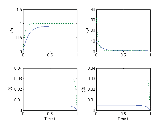
Stability plots will not be presented in order to save space, but numerical values regarding the stable Stability regions are analyzed in the e v plane for different values of the torsional spring rate c. Torsional damping constant k is taken as -50 Nm/rad/s.
Caster length evaries between -0.1 and 0.3 m, while the velocity v varies between 0 and 200 m/s. ctakes the values 0, -50000 and -100000 Nm/rad. Table 2 shows the percentages of the area of the stable region in the e v plane for the values of c considered. 1, there is more instability at small velocities and more stability at large velocities, while for > 0.1, there is more stability at small velocities and more instability at large velocities. Larger values of F z and v require larger values of ? k for stability and there is no instability for negative damping coefficients below 16 m/s. Generally speaking, shimmy occurs under a certain damping value, depending on the velocity. There is stability for all values of the damping constant k for small velocities for velocities below 16 m/s. Tables 3 and 4 show the percentages of the area of the stable region in the k ? v plane for the values of and F z considered, respectively. Effects of the variation of the caster length e, half contact length a and their ratio on stability boundaries are analyzed below. Increments and decrements in the stable portion of the e v and k v planes are presented quantitatively in tabular form.
0 0 1 = + + a s a 0 > n a 0 3 1 2 a a a a > 1 3 = a ( ) 5 2 2 c c a + ? = 4 3 1 5 2 1 c c c c c a ? ? = 3 5 1 0 vc c c a ? = ( ) 0 5 2 > + ? c c ( 3 0 ) 0 4 3 1 5 2 > ? ? c c c c c ( 3 1 ) 0 3 5 1 > ? vc c c ( 3 2 ) ( )( ) 3 5 1 4 3 1 5 2 5 2 vc c c c c c c c c c ? > ? ? + ? (33)10. ? ?
i. Effects of the half contact length on stability boundaries in the e v plane for different values of c This part of the stability analysis of the linear model is conducted in the e v plane, thus the effect of the caster length e is already contained within the calculations. For this reason, effect of the half contact length a on stability of the model will be analyzed.
Effects of 5 % and 10 % increase and decrease of the half contact length a are analyzed in this section.
A 5 % increase in the half contact length a from 0.1 m to 0.105 m leads to an increase in the unstable region in the e v plane, as can be seen by inspecting table 9. It is observed that there is a greater increase in the unstable region for large values of the torsional spring rate c .
A 5 % decrease in the half contact length a from 0.1 m to 0.095 m leads to a increase in the stable region in the e v plane, as seen by inspecting table 9.
There are almost no instabilities in the e v plane for a high torsional spring rate c. It observed that there is a greater increase in the stable region for large values of the torsional spring rate c.
A 10 % decrease in the half contact length a from 0.1 m to 0.09 m leads to a further increase in the stable region in the e v plane, as seen by inspecting table 9. As was the case for a half contact length of 0.095 m, there are almost no instabilities in the e v plane for a high torsional spring rate c and there is a greater increase in the stable region for large values of the torsional spring rate c .
The following table quantifies the amounts of increments and decrements in the stability of the e v plane for variations of the half contact length a. Values given for a half contact length of 0.1 m show how much of the analyzed region in the e v plane is stable.
Values given in the following lines for half contact lengths of 0.105 m, 0.11 m, 0.095 m and 0.09 m show how much of the analyzed region are stable and how much increment or decrement exists with respect to the stability of the system having a half contact length of 0.1 m.
Table 5 : Effect of variation of the half contact length on stability in the e v plane.
A 10 % increase in the half contact length a from 0.1 m to 0.11 m leads to a further increase in the unstable region in the e v plane, as can be seen by inspecting table 9. As was the case for a half contact length of 0.105 m, there is a greater increase in the unstable region for large values of the torsional spring rate c. ii. Effects of the caster length e and half contact length a on stability boundaries in the k v plane This part of the stability analysis of the linear model is conducted in the k v plane. Effects of the caster length e, half contact length a and their ratio on stability of the model will be analyzed. Effects of 5 % and 10 % increase and decrease of e and a and variation of their ratio are also analyzed. e a a effect of the half contact length ais already contained since 3a. For this reason, effect of the caster lengtheon stability of the model will be analyzed. Effects of 5 % and 10 % increase and decrease of e are analyzed in this section.
A 5 % increase in the caster length e from 0.1 m to 0.105 m leads to an increase in the stable region in
The k v plane, as can be seen by inspecting table 10. It is observed that there is a smaller increase in the stable region for large values of the relaxation length . Increase in the stable region is almost unnoticeable for relaxation lengths above 0.12 m.
A 10 % increase in the caster length e from 0.1 m to 0.11 m leads to a further increase in the stable region in the k v plane, as can be seen by inspecting table 10. As was the case for a caster length of 0.095 m, there is a smaller increase in the stable region for large values of relaxation length and the increase in the stable region is almost unnoticeable for relaxation lengths above 0.12 m.
A 5 % decrease in the caster length e from 0.1 m to 0.095 m leads to an increase in the unstable region in the k v plane, especially for low velocities, as seen from table 10. It is observed that there is a smaller increase in the unstable region for large values of the relaxation length . Increase in the stable region is almost unnoticeable for relaxation lengths above 0.12 m.
A 10 % decrease in the caster length e from 0.1 m to 0.09 m leads to a further increase in the unstable region in the k v plane, especially for low velocities, as seen from table 10. As was the case for a caster length of 0.095 m, there is a smaller increase in the unstable region for large values of relaxation length and the increase in the unstable region is almost unnoticeable for relaxation lengths above 0.12 m. Table 6 quantifies the amount of increments and decrements in the stability of the k v plane for variations of the caster length e. Values given for a caster length of 0.1 m show how much of the analyzed region in the k v plane is stable. Values given in the following lines for half caster lengths of 0.105 m, 0.11 m, 0.095 m and 0.09 m show how much of the analyzed region are stable and how much increment or decrement exists with respect to the stability of the system having a caster length of 0.1 m. RESULTS AND CONCLUSIONS 1. Results and conclusions about the variation of stability in the e v plane and recommendations A 5 % increase in the half contact length a leads to an increase in the unstable region in the e v plane.
A 10 % increase in the half contact length a leads to a further increase in the unstable region in the e v plane.
A 5 % decrease in the half contact length a leads to an increase in the stable region in the e v plane.
For the parameters considered, there were no instabilities in the e v plane for a high torsional spring Rate c.
A 10 % decrease in the half contact length a leads to a further increase in the stable region in the e v plane. For the parameters considered, there were no instabilities in the e v plane for a high torsional spring rate c.
The increments in the stable and unstable regions are greater for large values of the torsional spring rate c.
Increments in the half contact length lead to increments in the unstable region in the e v plane.
In other words, increasing the half contact length decreases stability. Decrements in the half contact length lead to increments in the stable region in the e v plane. In other words, decreasing the half contact length increases stability.
2. Results and conclusions about the variation of stability in the k v plane and recommendations A 5 % increase in the caster length e leads to an increase in the stable region in the k v plane.
There is a smaller increase in the stable region for large values of the relaxation length such that the increase in the stable region is almost negligible for relaxation lengths above 0.12 m.
A 10 % increase in the caster length e leads to a further increase in the stable region in the k v plane. There is a smaller increase in the stable region for large values of relaxation length and the increase in the stable region is almost negligible for relaxation lengths above 0.12 m. A 5 % decrease in the caster length e leads to an increase in the unstable region in the k v plane, especially for low velocities. There is a smaller increase in the unstable region for large values of the relaxation length such that the increase in the stable region is almost negligible for relaxation lengths above 0.12 m.
A 10 % decrease in the caster length e from leads to a further increase in the unstable region in the k v plane, especially for low velocities. There is a smaller increase in the unstable region for large values of relaxation length and the increase in the unstable region is almost negligible for relaxation lengths above 0.12 m. Increments in the stable and unstable regions are smaller for large values of the relaxation length . Increments in the caster length lead to increments in the stable region in the k v plane. In other words, increasing the caster length increases stability. Decrements in the half contact length lead to increments in the unstable region in the k v plane.
In other words, decreasing the caster length decreases stability.
![Figure 1 : a. Nose landing gear model [30],](https://engineeringresearch.org/index.php/GJRE/article/download/100101/version/100101/3-Stability-analysis-of-a-landing-gear-mechanism_html/2002/image-2.png)
| Parameter | Description | Value | Unit | |||||
| v | velocity | 0?80 | m/s | |||||
| a | half contact length | 0.1 | m | |||||
| e | caster length | 0.1 | m | |||||
| I | z | moment of inertia | 1 | kg m 2 | ||||
| z F | vertical force | 9000 | N | |||||
| c | torsional spring rate | -100000 | Nm/rad | |||||
| c | F | ? | side force derivative | 20 | 1/rad | |||
| c | M | ? | moment derivative | -2 | m/rad | |||
| k ? ? | = | a 3 | torsional damping constant tread width moment constant relaxation length | 0?-50 -270 0.3 | Nm/rad/s Nm 2 /rad m | |||
| ? | g | limit angle of tire moment | 10 | deg | ||||
| ? | limit angle of tire force | 5 | deg | |||||
| Percentage of stable region |
| Percentage of stable region | |
| =0.02 m | 78.3 % stable |
| =0.07 m | 65.4 % stable |
| =0.12 m | 61.3 % stable |
| =0.17 m | 60.7 % stable |
| =0.22 m | 61.4 % stable |
| =0.27 m | 62.9 % stable |
| =0.32 m | 64.4 % stable |
| Percentage of stable region | |||
| F z = 0 N | 72.5 % stable | ||
| F z = 5000 N | 58.5 % stable | ||
| F z = 10000 N | 45.1 % stable | ||
| F z = 15000 N | 32.5 % stable | ||
| 3. Effects of t | he caster length | and half contact | |
| length on stability boundaries | |||
| Stability analysis of a landing gear mechanism with torsional degree of freedom |
| a e / =1 |
| 25 | ||||||
| Volume XII Issue v v v v I Version I | ||||||
| D D D D ) D | ||||||
| ( | ||||||
| z F =0 N z F =5000 N z F =10000 N z F =15000 N | 72.5 % stable 58.6 % stable 45.3 % stable 32.8 % stable | 72.5 % stable 58.5 % stable 45.2 % stable 32.6 % stable | 72.5 % stable 58.5 % stable 45.1 % stable 32.5 % stable | 72.5 % stable 58.4 % stable 45 % stable 32.3 % stable | 72.5 % stable 58.4 % stable 44.9 % stable 32.2 % stable | Global Journal of Researches in Engineering |
| a e / =0.9 | ||||||
| e =0.081 m | e =0.09 m | e =0.1 m | e =0.11 m | e =0.122 m | ||
| a =0.09 m | a =0.1 m | a =0.11 m | a =0.122 m | a =0.135 m | ||
| z F =0 N | 72.5 % stable | 72.5 % stable | 72.5 % stable | 72.5 % stable | 72.5 % stable | |
| z F =5000 N | 58.8 % stable | 58.6 % stable | 58.5 % stable | 58.5 % stable | 58.5 % stable | |
| z F =10000 N | 45.7 % stable | 45.4 % stable | 45.2 % stable | 45.2 % stable | 45.4 % stable | |
| z F =15000 N | 33.2 % stable | 32.7 % stable | 32.5 % stable | 32.3 % stable | 32.3 % stable |